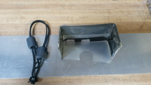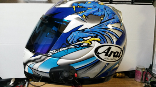

This GPS is not intended for outdoor use so I made a weather/glare shield for it and attached the Garmin Nuvi 1390T to my windshield using the factory suction cup mount. For insurance I also attached a bungie cord from the GPS and my handlebar.
Through temperatures ranging from 65F in the east to 116F in the west and heavy rains in the east to bone dry weather in the west, on pavement smooth as silk to bone jarring cobblestone chunks of concrete, the Garmin Nuvi 1390T GPS performed, and continues to perform, flawlessly. A testament to the quality of the construction of this piece of 'consumer' electronics. I did have to reseat the suction cup mount one time in the 7,300 mile trip and that was after going from a very hot desert environment to a very cool mountain environment. The GPS did not fall off the windshield it just took very little pressure to remove it.
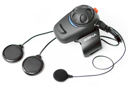
Because I was planning another motorcycle trip, I was in the market for an additional GPS unit I could dedicate to the motorcycle and that is when I discovered that I would have to spend in excess of $600.00 to get a Garmin GPS with Bluetooth Audio Out compatible with my Sena SMH5 headset. I refused to do so and thus this project to route the Garmin Nuvi audio to my Sena SMH5 Bluetooth headset was born. Actually this modification should work with almost any GPS and Bluetooth or wired headset or a communications / intercom device like the J&M CB radio.
There is no fancy switching / muting of the GPS internal speaker or syncronized power up and down of the GPS and the Bluetooth transmitter. You can add these features if you choose by changing some of the hardware but, you will also add complexity and cost, the two things I wanted to avoid. Heck, if you wanted to pay the price for a super custom installtion, you could have those features AND eliminate the cable altogether. However that requires extensive modification to the GPS case and wiring which, in my opinion, may not be as reliable as the cable installation. This modification will void your warranty, if you have any!
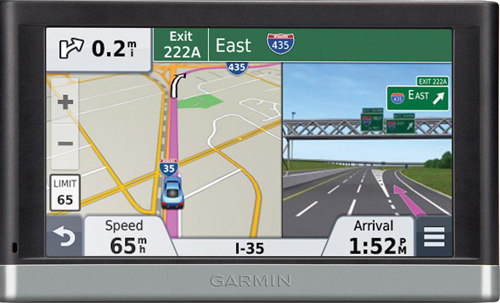
When compared to the Nuvi 1390T, this GPS has a little larger five inch screen, it has 'Voice Command' for voice control and it has the Traffic Information Receiver built into the unit rather than into a rather bulky dual purpose power cable.
This unit does not have the bluetooth communications ability to talk directly to the Sena SMH5 headset. If you are interested, some of the technical details on Bluetooth communications can be found in PDF format here. You can read the full article at The Headphone List. Please note that the following modification does not disable or mute the GPS internal speaker, it will continue to operate normally.
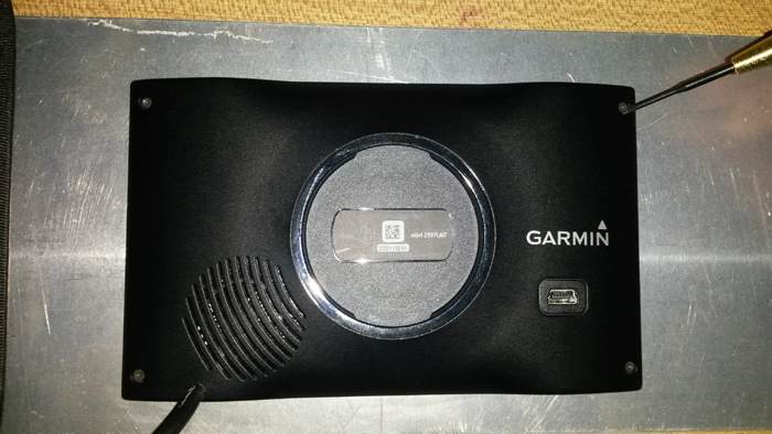
My plan was to feed the audio from the Garmin Nuvi 2597LMTs
speaker into the Anker MB220 and transmit it in the format that the Sena
SMH5 Bluetooth headset wants.
Update: Note that Ankor is no longer making the MB220. Doing a search for "Bluetooth transmitter and receiver" turned up a number of different devices that claim to work the same way. Most popular recently is the Taotronics TT-BA07 which works well. Please note that I have not tested any of the others. A simple test would be if it 'Pairs' with your headset it should work.
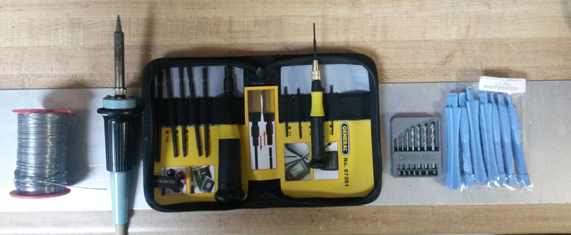
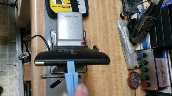
1 - T5 torx bit to remove the screws
from the back cover of the GPS. *
* Note: Your GPS may have a different type of screws holding the back on.
2 - 4 inch Pieces of 30 AWG wire wrap wire or 28 AWG hook-up wire. 1 - Two inch long piece of 1/4 heat shrink tubing. 1 - Two inch long piece of 1/8 heat shrink tubing. 1 - 47uf 25vdc capacitor.** 1 - Tube of GOOP sealant or sealant of your preference. * Note: You need to determine if you are going to mount the Anker MB220 directly on the back of the Garmin Nuvi 2597LMT or at some other location and cut the stereo cable to the length needed. ** May be a different UF value for your GPS. Higher voltage value is fine.
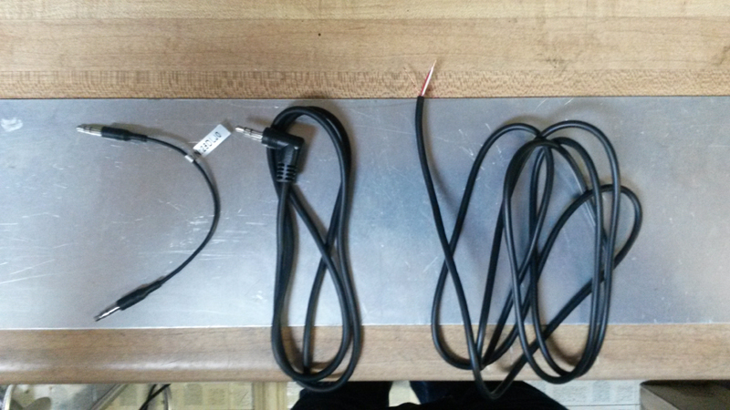
In the photo below the first cable is the one that came with and Anker MB220 which I felt would not hold up to the rigors of a motorcycle environment so I opted for a heavier approx. 3/16 inch (0.147 or 3.73mm) stereo cable. Note that you need a stereo cable if you want to get sound to both speakers in the headset.
The second cable is a standard stereo cable that had a jack at both ends. I removed the jack from one end of the cable and bared the wires as shown on the third cable.
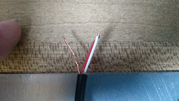
The stereo cable shielding should be twisted together as shown and some shrink tubing put over it leaving about 1/8 inch of the end exposed. This wire will be soldered to the negative (-) side of the speaker in the GPS receiver. This is normally where a black wire is connected to the speaker. Using a soldering iron, tin the ends of both wires in preparation for soldering them to the capacitor and the speaker.
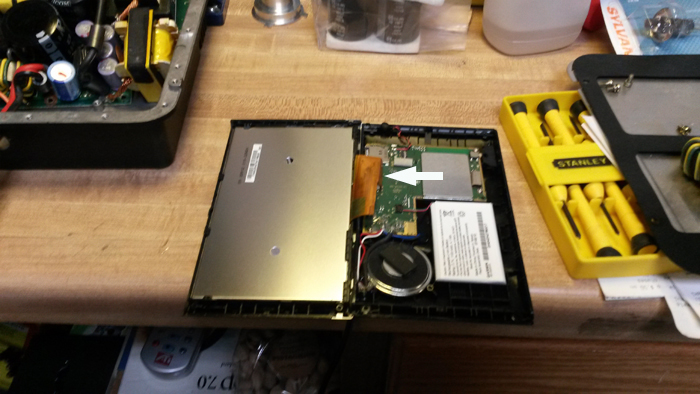
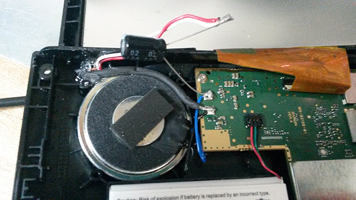
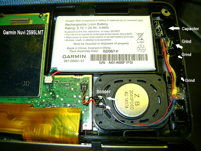
Be careful that you do not pull the ribbon cable that connects the display screen to the electronics out of it's connector as it can be problematic getting it back in. It is the gold thing in picture below (see arrow).
That white tag you see on the lower right in the picture is the battery and that round black thing to the left of the battery is the speaker.
It allso allows for a gentle bend where the cable exits the GPS housing and provides the cable some level of protection from snagging and abration as it is 'hidden'.
The stereo cable I used measured approximately 0.147 (3.73mm) so I chose a #26 drill bit which would make a hole that would allow the cable to easily slip through but not be too big. To make things easier I inserted the stereo cable into the hole and double checked the length of the wires going to the speaker. In fact I made sure that they were a little bit long. I also applied the Goop sealant to the cable and the hole and let it dry before soldering the wires so that I would not get fresh sealant all over the inside of the GPS while trying to do the soldering. I left the GPS open over night to allow the sealant to 'gas off' before soldering the wires to the speaker.
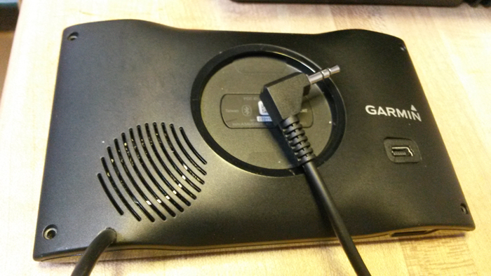
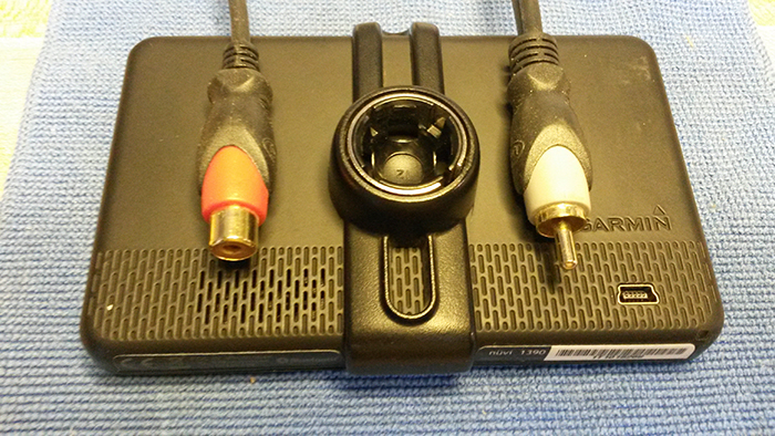
The next day I routed the wires and trimmed them to fit making note of the tight fit when putting both halves of the GPS back together. Please note that while I used a 90 degree male stereo jack, a straight male stereo jack or, if you want to connect the GPS to something like a J&M CB radio using their male adaptor cable, a female stereo jack can be used .
Using a female stereo jack you can even plug your wired headset or earbuds directly into your GPS if you do not want to go the wireless route or even plug in a amplified stereo speaker. If you wish, a single RCA jack for mono can be used. If you add a RCA 'Y' cable adaptor you can even configure right and left channels.
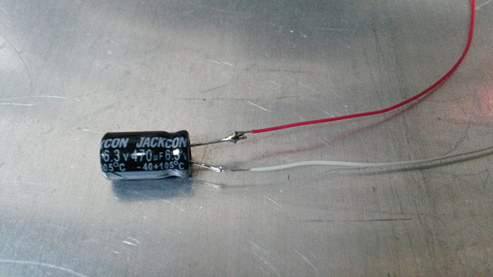
What happens then is the amplifier over-heats and truns off and back on very quickly trying to cool off. That is indicated by 'stuttering' audio. After this happens a few times the amplifier may self destruct from the abuse. You also have two different electrical ground potentials, one in the GPS and one in the Bluetooth transmitter which sometimes will not work correctly when directly connected together via the cable ground wire. The capacitor basically isolates (hides) the second speaker from the amplifier. Better to test and install it while you have the unit apart the first time rather than having to tear it apart again. In the picture below I used a 470uf 6.3v coupling capacitor for testing. You can see that the red and white wires of the stereo cable have been soldered to the negative (-) lead of the coupling capacitor. The positive (+) lead of the coupling capacitor has been soldered to the light blue speaker wire.
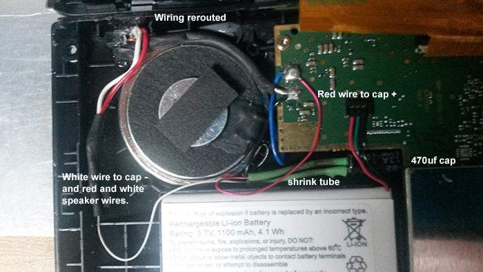
After testing with capacitors I had on hand, the value of capacitor that proved to work best for me was a 47uf 25vdc which gave decent 'crisp' audio quality, that can be heard above road and wind noise, and good volume from the Sena SMH5 Bluetooth headset. Note that while this value works well for me it may be different for you because the capacitor also acts like a bandpass filter that impacts the 'crispness' of the audio. Try it as a starting point and adjust it to your sound preference. The twisted shield wire of the stereo cable has been covered with black shrink tubing and soldered to the black speaker wire. Go to the Pairing and Communications Testing section for the procedure to test your audio quality. Note that you only have to perform the 'pairing' procedure once. After that, 'pairing' will be performed on power-up.
I soldered kynar wire 30awg (wire-wrap wire) to the shortened leads of the capacitor. Red to the Positive (+) lead of the coupling capacitor and white to the negative (-) lead of the capacitor. If you cannot find 30awg kynar wire you can use 28awg hook-up wire.
For safety sake slide a piece of shrink tube over the bare leads of the capacitor. Bare the other ends of the kynar wire and using a soldering iron, tin the ends of the wires. Solder the red wire from the coupling capacitor to the speaker pad with the blue wire.
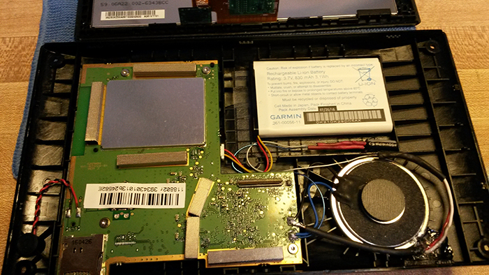
If you zoom in on the photo of the NUVI 2597LMT above, it will be easier to see the placement of the coupling capacitor in-between the battery and the main board. Try to keep the wiring off of the speaker and the battery or it will be pinched when you put the covers back together. As you can see the wiring layout and routing is quite simple. Now, for comparison, look at the NUVI 2595LMT below.
If you zoom in on the NUVI 2595LMT you will notice that you will have to grind or cut notches in the internal webbing of the case to get clearance for the wires and the capacitor installation. There is absolutely no spare room in this unit. The NUVI 2599LMT is the same. Route the wiring so that it is not on the battery or the speaker magnet. The NUVI 2689LMT shown below has a 6 inch screen and has a lot of room to work with with the standard 830mah battery which makes for an easy installation of the coupling capacitor and wiring. With the 1500mah battery installed your options are obciously reduced. Note that I did remove the display screen ribbon cable to make things easier.
No matter which unit you are working on, watch how much solder you apply to the speaker wire pads on the pc board as too much will cause them to short out against the metal cover for the display. For safety, place a piece of electrical tape over the solder joints if one is not there already. Wait, wait, wait..... don't close the GPS up yet. You can put both halves together but do not snap it shut until you have actually tested it to make sure it works correctly.
1 - Please make sure that if the GPS has Bluetooth capability it must be set to the 'OFF' position. 2 - Make sure that your Bluetooth transmitter is not connected to a USB port for power, it should be running on its internal battery. Most units will go into 'charge mode' and will not transmitt or pair when connected to a USB port.
1 - Make sure that the Anker MB220
(or whatever you are using) is fully charged.
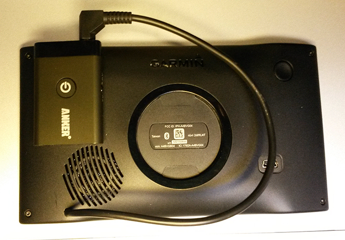
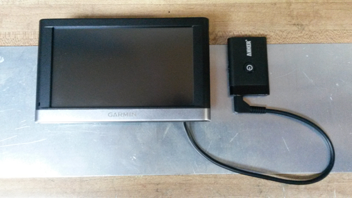
There are still some options to consider. You can attach the Anker MB220 to the back of the Garmin NUVI 2597LMT with double sided tape if you are only going to use the MB220 with that GPS. You can also attach it with stick on velcro strips so that you can remove the MB220 and use it on other devices you want to send or receive audio, music or video to/from via Bluetooth.
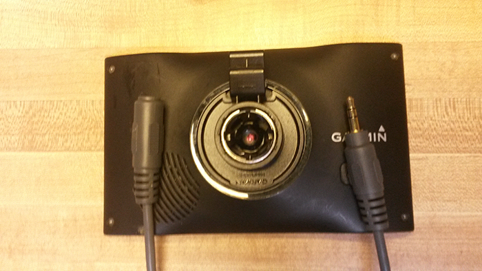
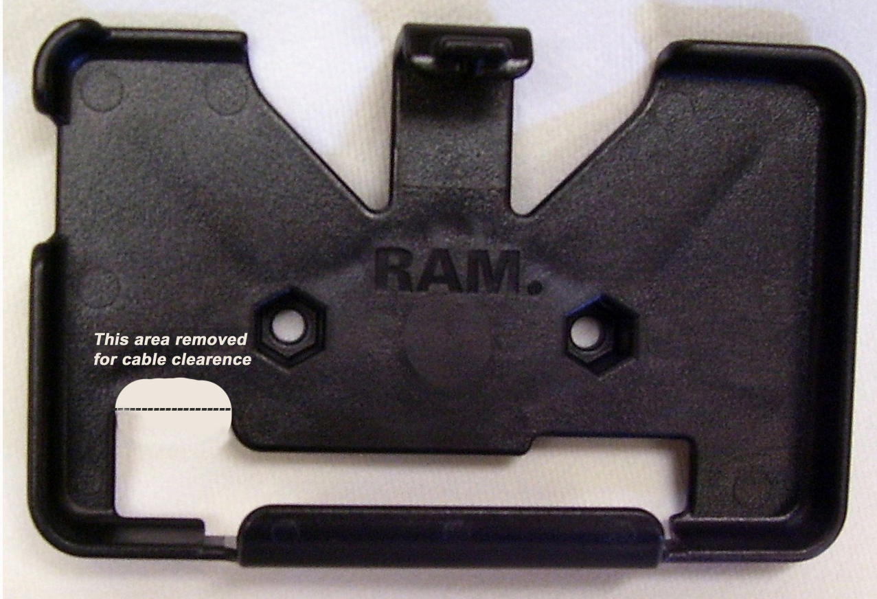
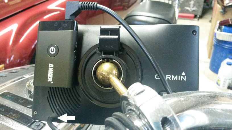
If you are using a 'ball' mount such as below, no modifications are necessary to accomodate the cable exit location (see arrow).
Note that with the 90 degree stereo jack the chance of the cable being pulled out of the Bluetooth transmitter accidently is minimized as well as it has a lower profile than the straight jack in this particular installation.
I purchased the Anker MB220 Bluetooth Transmitter and Receiver. I purchased a 6 ft long 3.5mm (1/8 in) stereo cable with jacks. I used a 47uf 25vdc capacitor from my 'miscellaneous' parts box. I used a company soldering iron and solder. I used some company shrink tube. I used some company sealant. I made a new weather/glare cover using leftover material. ============================================================ Total costs = Less than $200.00 Cycle GPS Cost = $600.00 ====== Savings = $400.00
The following information is needed: 1 - How long do you want the cable to be in the range of 8 to 32 inches. 2 - Do you want a straight or 90 degree male stereo jack? 3 - Do you want a female stereo jack? (Used with J&B CB and other intercoms.) 4 - Do you want a male or female RCA mono jack instead of a stereo jack? 5 - Are you sending a cradle mount? That $55.00 USD price includes the cost of the stereo cable and jack, the coupling capacitor and labor. It also includes the cost of modifying your cradle mount, if needed. It does notinclude the cost of insured shipping or any type of cable adaptors.
You can also pre-pay the cost of return shipping and put the return label in with the GPS and your check for $55.00 USD when you ship it to us. If you choose not to insure your shipment to us, we will return it the same way and, we will reject any and all claims for responsibily if it is lost by the carrier. You can click here
As there are no moving mechanical parts or active electronic parts, only the glue holding the audio cable in place could possibly fail, and that might possibly be from over stressing the cable. Even if the glue fails the GPS modification should continue to perform. You should be able to hear the GPS audio until or unless the audio cable jack has been damaged or the audio cable has been severed from its internal GPS connection. As far as support, we will provide assistance without charge only to those that had us perform the GPS modification. But first, please read and perform the steps in the Pairing and Communications Testing section on this page again and, if you still can't get things working, send us an email explaining the problem you are having.
For those of you who insist on calling for any installation assistance, there will be an additional charge of $75.00 USD for a Priority Consultation. Please note that if you have damaged the heads of the screws on the back of your GPS and they cannot be removed with a standard torx or philips driver, there will be an additional charge of $35.00 USD to remove and replace them.
|