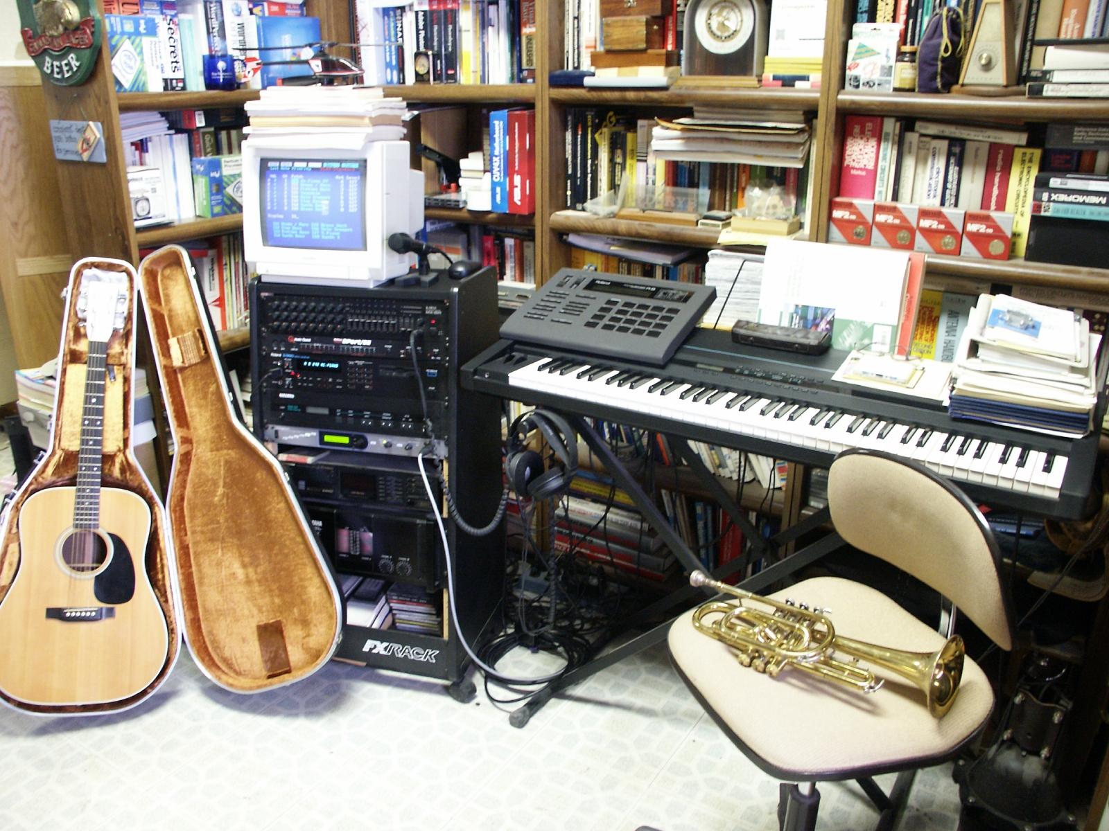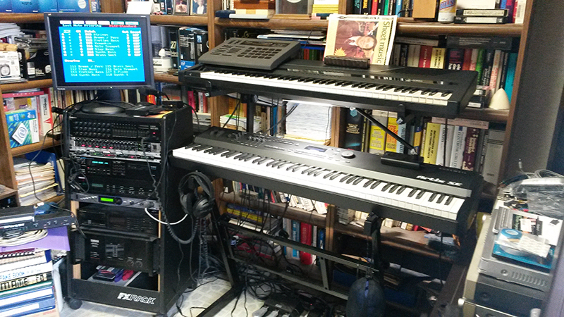

In short, we upgraded the patch bay to a M-Audio Midisport 8x8 because we could not get updated drivers for our old Music Quest 8 Port/SE anymore. We added the Kurzweil Artis 88 key keyboard and added a Behringer 16 port mixer to our mixer bank.
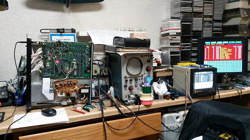
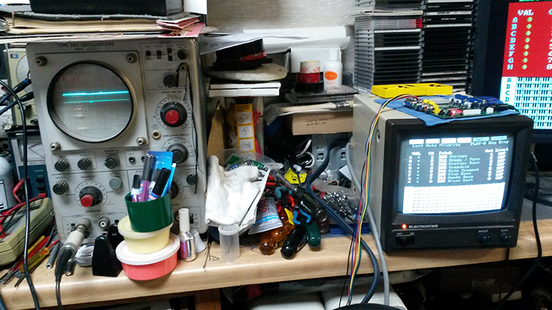
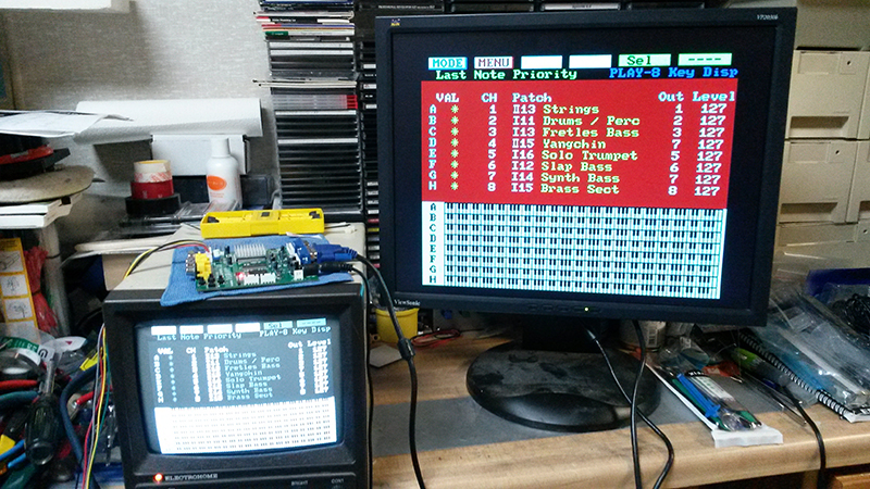
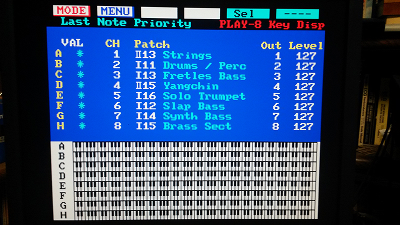
The one big thing that really needed upgrading was staring us right in the face, that was the old RGB display monitor. It had served us well since 1987 but going from our super high resolution monitors on our computers to the old RGB display on the Roland S-550 was somewhat of a visual letdown. So the project to see if and how we could upgrade the Roland S-550 digital sampler to use a modern LCD display was hatched because we still find this digital sampler very handy because of its versatility. Roland S-550 Video Signal Time to stop guessing and determine what is actually going on so let's get technical and hook up the gear. Starting on the left is the Roland S-550 digital sampler, next is an analog oscilloscope, after that is a black and white composite video monitor and finally is a digital LCD monitor.
We had a monitor connected to both the composite video and the RGB video ports on the S-550 to make sure the onboard video processor was stable and could be verified by the B&W monitor at all times. A quick check with the scope showed that black and white composite signal was indeed standard and verified by the B&W monitor.
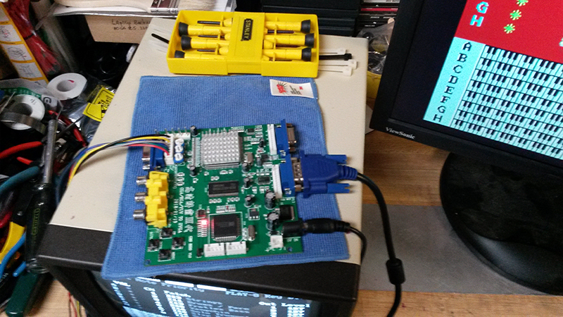
On first pass we did notice a difference in the S-550 RGB composite sync signal and try as we might we could not get a stable picture on a color analog or digital monitor. Our next option was to try a video converter. JAMA Board VGA Or SCART HDMI ? Basically there are two options, a JAMA board, designed to convert the video from old arcade video games to digital output or, a european SCART converter used stateside to convert old Sega console games to digital video output. SCART comes from Syndicat des Constructeurs d'Appareils Radiorécepteurs et Téléviseurs, "Radio and Television Receiver Manufacturers' Association" a French-originated standard. First we tried the JAMA board because it was easily available, dirt cheap and very easy to hook up. During the hook up we noticed that there was something different in wiring of the Horizontal and Verticle sync coming from the S-550 and made a note of it.
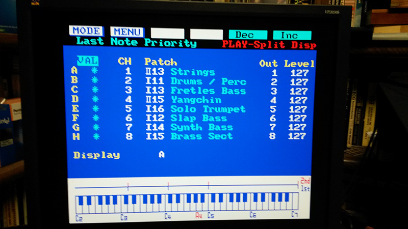
After adjusting all of the controls for the best picture on the LCD we were not totally pleased with the video quality as there were artifacts around all of the characters and a bit of shimmer in the multi-keyboard area of the screen.
For casual work this board may be fine but for work of any length we did not believe the display would be suitable.
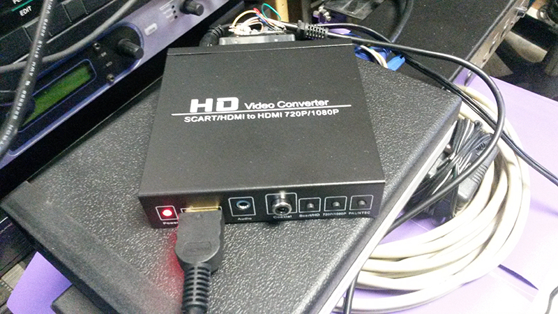
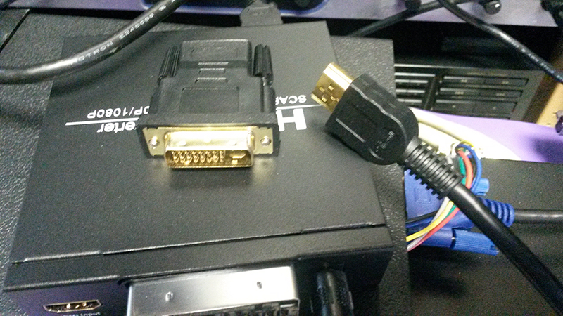
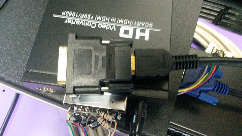
Another thing we liked is that this converter has HDMI output which, with a simple adaptor, allows you to use the newest DVI or HDMI monitors.
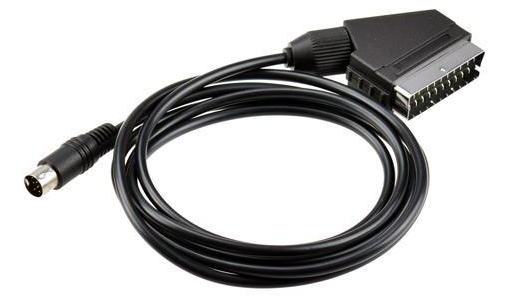
First off, when doing the basic research for this cable, there were multiple postings about the terrible noise corruption in the monitor display caused by using 'cheap' unshielded SCART cables. Being curious by nature we purchased a super double shielded cable with all metal hoods as well as a very inexpensive unshielded cable. Initially the super double shielded cable with all metal hoods looked quite impressive. The first negative came with the size and weight of the cable, a bit cumbersome to work with.
Next was the fact that we were only going to use 7 of the 20 wires in it. Last was the fact that we needed to do substantial modifications to this cable to use it as we wanted. Our inexpensive cable was chosen for the fact that it was designed to be used with a Sega Genesis console and had impedance matching and decoupling on the color signal inputs built into the SCART connector hood.
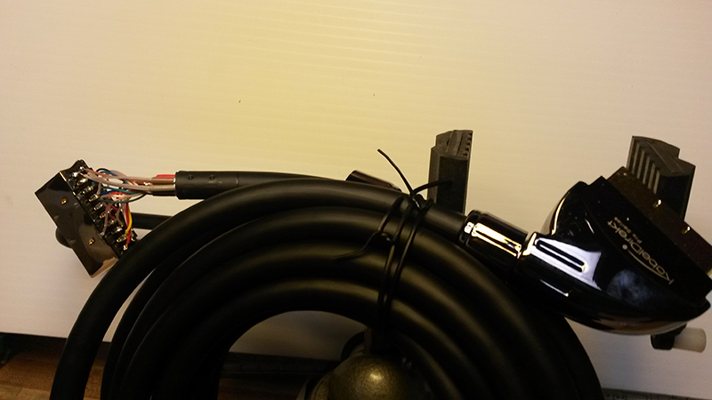
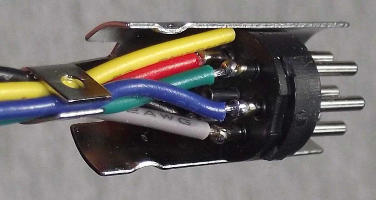
What it did not have was any shielding which in reality we did not think would be a problem because of the low voltages and frequencies we were dealing with. If there was a noise problem a couple of ferrite beads should take care of it. Please note that this cable will not work as it is with the Roland S-550 because the wiring of the 8 pin DIN connector is not correct. Modifying The SCART Cable The picture below is shown only as an example of the connector and is not wired correctly. The correct wiring is shown in the wiring diagram below.
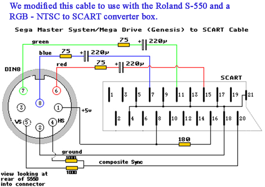
Finally we wanted to impedance match all of the video inputs to 75ohms and decouple the video signals from the S-550. The wiring diagram below shows how it was done.
On the Roland S-550 eight pin DIN connector notice the
non-sequential pin numbers starting clockwise at the notch with:
Pin 6 = Red ____________ To SCART pin 15 through 75 ohm
and 220u cap.
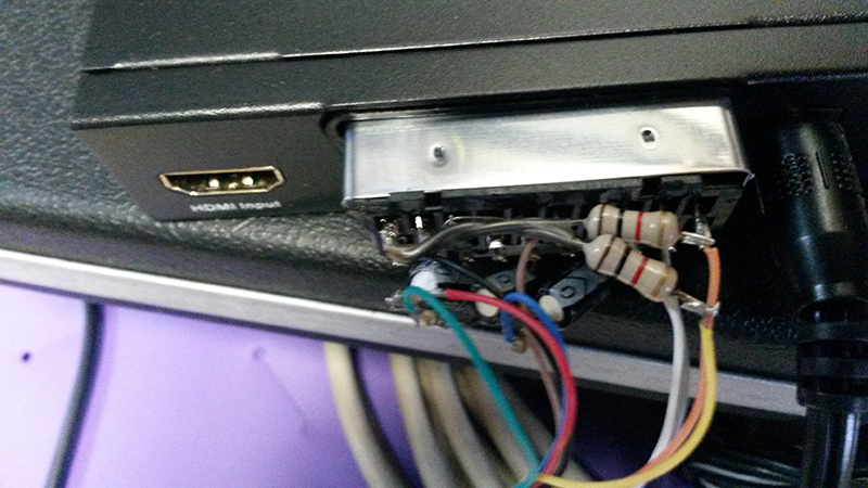
The view of the round connector is from looking at the back the Roland S-550. The view of the SCART connector is from looking at it from the wire side under the hood. The only devices that need to be added to the inexpensive cable are: (1) a new 8 pin DIN connector as the one that came on the cable will have to be cut off and cannot be saved. For reference a Switchcraft 15BL8MX is the correct 270 degree connector which is available from Digi-Key. (2) the two 1000 ohm (1K) resistors at the bottom left of the layout. The resistors are installed in the SCART connector and are contained under the hood (see photo below). The name of the cable we modified was a Sega Genesis 1 / Mega Drive 1 / Master System RGB SCART Cable (270). You can search for it specificlly if you want to use what we did. Remember the 'something strange' about the Roland S-550 RGB signal mentioned at the beginning of this post? Well it turned out that Roland split the composite Horizontal and Verticle sync signal in two. To overcome that, the signals are recombined using the two 1K resistors for normal composite sync as shown in the photo below. You can also see the capacitors and a slight bit of the resistors all of which fit in the SCART connector hood.
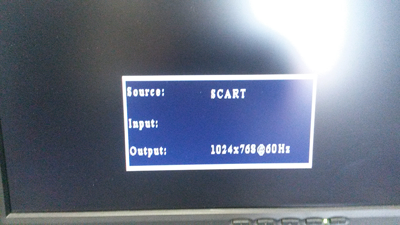
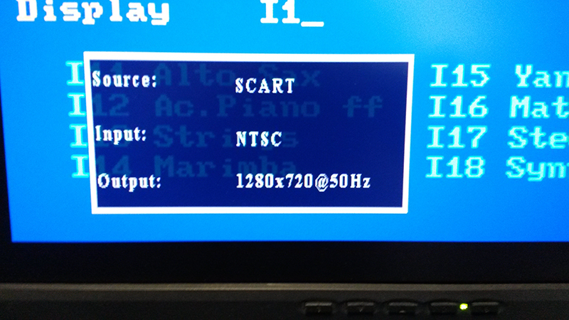
One final thing, if you are not getting any video output, remember to set the Source to SCART and not HDMI. To finish the setup just follow the simple instruction manual and set your preferences.
Note that to date we have not found a need for any additional electrical or electronic noise suppression thus negating the need for a shielded cable or ferrite beads. The impedance matching resistors and decoupling capacitors seem to be sufficient. (Click or Tap on the number to dial) Like Us? Rate Us! on Yahoo, Bing, Google, Yelp, Facebook, Whatever Last Updated 02-15-2022 If you have comments or suggestions, email us at supportgroup@m-p-c.com Copyright © 2017-2023 Multi Path Communications Van Buren Township, MI 48111 All rights reserved Computer Repairs - Upgrades - Custom Builds - Virus Removal - Software Backup, Installation & Upgrades |